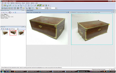
Starting with photo one I marked the visible points of the box.

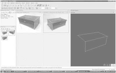
In reference mode, using photo one as the reference image (shown by the blue boundary around the photo), I marked the corresponding points on photo 2.
 By opening the 3d view I could see how much of the box had been built.
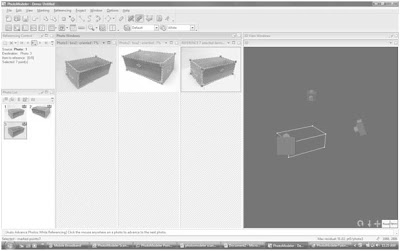
Again using photo one as the reference image I marked the corresponding points on photo three. Camera position were now solved and could be seen in the 3d view port.
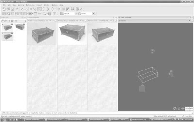
 I drew the missing lines onto photo three, then using photo three as the reference image I marked the corresponding points onto photo two. The box was then shown as complete in the 3d model view.
  Using the surface tool I added surfaces to each face of the box, which showed as white planes in the 3d view.
  Using the 3d view options I turned on fast textures and the program mapped images from the original photos onto the 3d view. The image was warped warped.
  By changing the view option to quality texture I got a more accurate representation of the original box.
 I then zoomed in on each point of my box in the original photos and adjusted my frame to better fit the image increasing the accuracy of the model.
 Finally I used the project menu to open up the scale/orientate window. Using this window I set the units of my project and used a known length to set a scale. I also set the horizontal and vertical directions.
The program automatically calculated the measurements of the rest of the box. I could then find out any measurement simply by clicking on it.
 The model was complete and ready to be exported for use in other cad software.